Digital Download
$99.99
Add to Cart
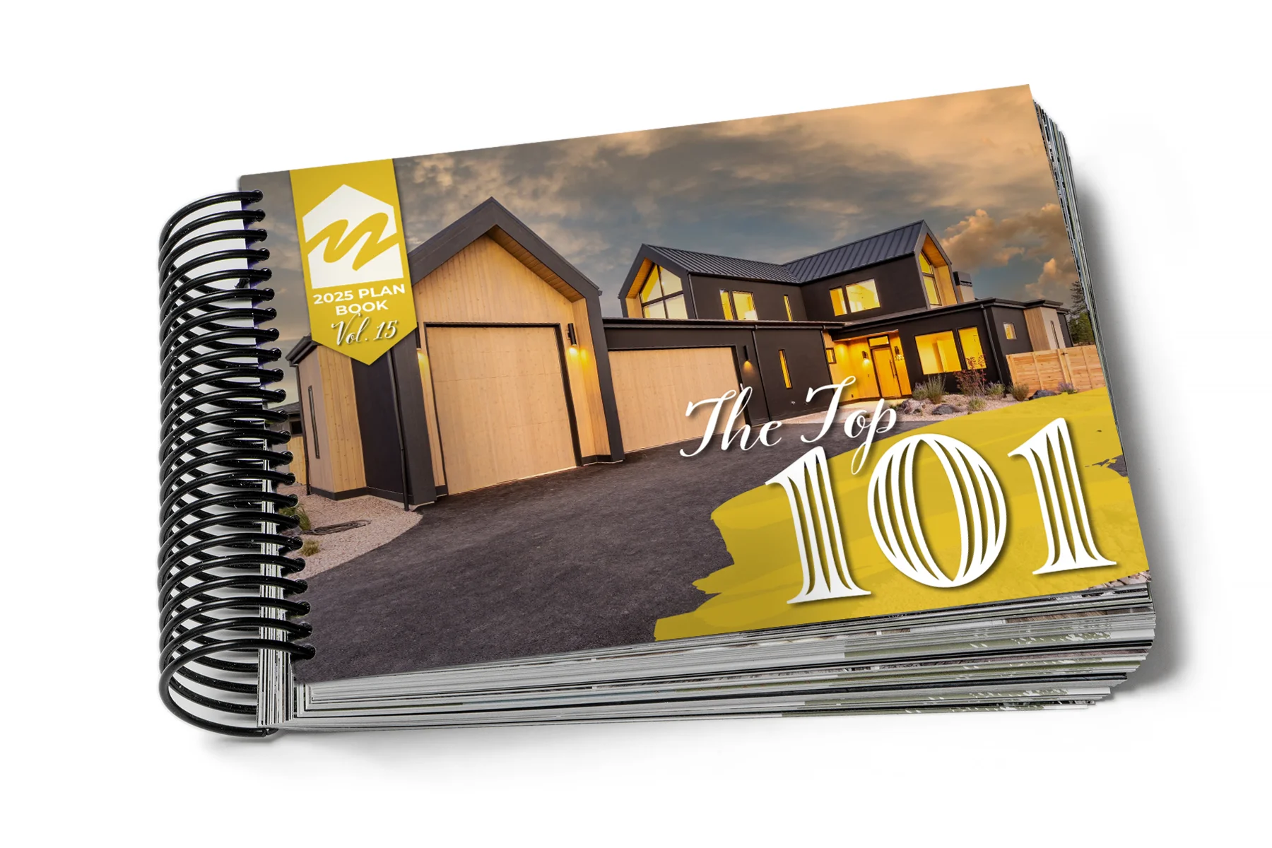
Spiral Bound Book
$139.99
Add to Cart
Ask a Question?
Click here
Craftsman style design taking shape in the Discove
Modern Farmhouse The 2026 Plan Book 📕#muddyriver
Northwest style design slated for construction lat
Does social media really work? Does it accomplish
The Great American Farmhouse 👍 Simple Lines. Propo
Another timeless design from Muddy River Design 👍
Let's Connect
Facebook-f
Instagram
Twitter
Midtown
244 SE Miller Avenue
Bend, OR 97702
